GBC FP 2.5D RetroPixel Install Guide
This kit has optional soldering, you only have to solder the wires if you would like button controls for the OSD and brightness.
This kit requires you to use either the NES shell that is provided with the kit, or another one of FunnyPlaying's RetroPixel compatible shells
Ensure you have all the parts included with your kit. See below:
The NES/VES RETRO PIXEL LAMINATED LCD KIT Includes:
- 1 x Laminated GBC IPS Kit or Laminated 2.5D GBC IPS Kit
- 1 x Ribbon Cable
- 1 x Touch ribbon cable
- 2 x 20mm Wire
- 1 x 5mm Wire
- 1 x NES Style GBC Shell
- 1 x Set of NES Style GBC Buttons
- 1 x Set of GBC Membranes
Before You Proceed
- Fully disassemble your AGB Game Boy Color
Installing your IPS kit, bending the ribbon cables, soldering, or applying any adhesives in this kit will void the warranty and return policy. Fully test your kit before proceeding.
- LCD may break if put under too much pressure or dropped. Please exercise extreme caution when installing.
- Damage to console or LCD may occur if you do not trim the cartridge port pins. Exercise caution when trimming pins, wear eye protection to protect from pin debris when cutting the metal. Damage caused by these pins are not covered under our return or exchange policy. Trim the pins of your Gameboy's cartridge slot flat so that they don't interfere with any parts of the kit. We also recommend placing some Kapton tape over the trimmed pins to prevent any shorts.

First we will remove the control board and ribbon cable combo from the screen, we are going to tin the pads with solder. There are two pads on the front and one pad on the back to tin.

Once you've tinned the pads, you can solder the wires into place. The shorter wire will go on the back of the ribbon cable for the power connection.

Next we are going to remove the tape from the adhessive from the screen and place it into the shell.


Now, reconnect the ribbon cable on the back of the display.

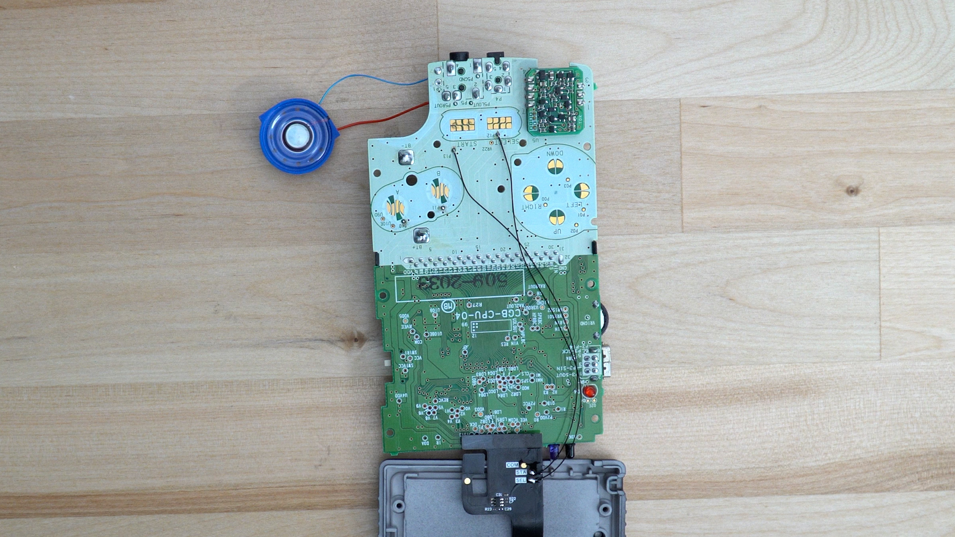
The buttons and their membranes then get put into the console in preperation for finishing the mod. After that we are going to solder the two wires for button controls. Start will go to P13 and Select will connect to P12.

We recommend using kapton tape to hold the wires out of the way of the membranes. If they get under the membranes they could impact their ability to work, as well as how the buttons feel.

After securing those two connections, you can place the motherboard of the console back into the console and insert the ribbon cable at the top of the console.

The final step of this install is to solder the power wire from the back of the ribbon cable to the second pin from the bottom of the power switch.

Once that is done, you can reassemble your console as normal and give it a test!

Is the logo on your laminated lens not illuminating properly? Try these steps to resolve it.
- Hold down the touch sensor longer than you would for any of the effects. Basically just an extra long press (at least 10 seconds) until the issue disappears.
- Hold down start and select for a long press (at least 10 seconds) as well. This is supposed to factory reset the lens.
If the issue does not get resolved with one of these methods, please reachout to support at [email protected]

