GBA SP IPS V2 & V2 TV Out Hispeedido | Install Guide
This is our install guide for the V2 HISPEEDIDO IPS kit and the V2 TV Out version IPS kit for GBA SP.
Hand Held Legend earns commissions for Amazon purchases made through links in this post.
For audio output with the AV kit, you will need to purchase a headphone adapter.
All shells will require trimming. Please see prequisite steps.
- Flush cutters
- Pre-trimmed GBA SP Shell
- Y0 Tri-point screwdriver
- J0 screwdriver
- Plastic spudger
- Tweezers
- Fully disassemble your GBA SP (Hinge removal not necessary)
- Dry test your IPS kit
Installing your IPS kit, bending the ribbon cables, soldering, or applying any adhesives in this kit will void the warranty and return policy. Fully test your kit before proceeding.
Ensure that you have all of the included parts. See below.
- IPS laminated panel
- IPS control PCB (two touch sensors are pre-soldered)
- PCB Insulation film
- Double sided adhesive strip
- IPS Ribbon cable
- Wires for optional brightness control and TV-Out function
- AV cable (TV version only)

Start by inserting the IPS ribbon cable into the IPS control PCB connector. It goes dark side facing up. Incorrect orientation will result in no picture on the display. Take care to ensure the cable is fully inserted. Carefully close the ribbon cable latch.

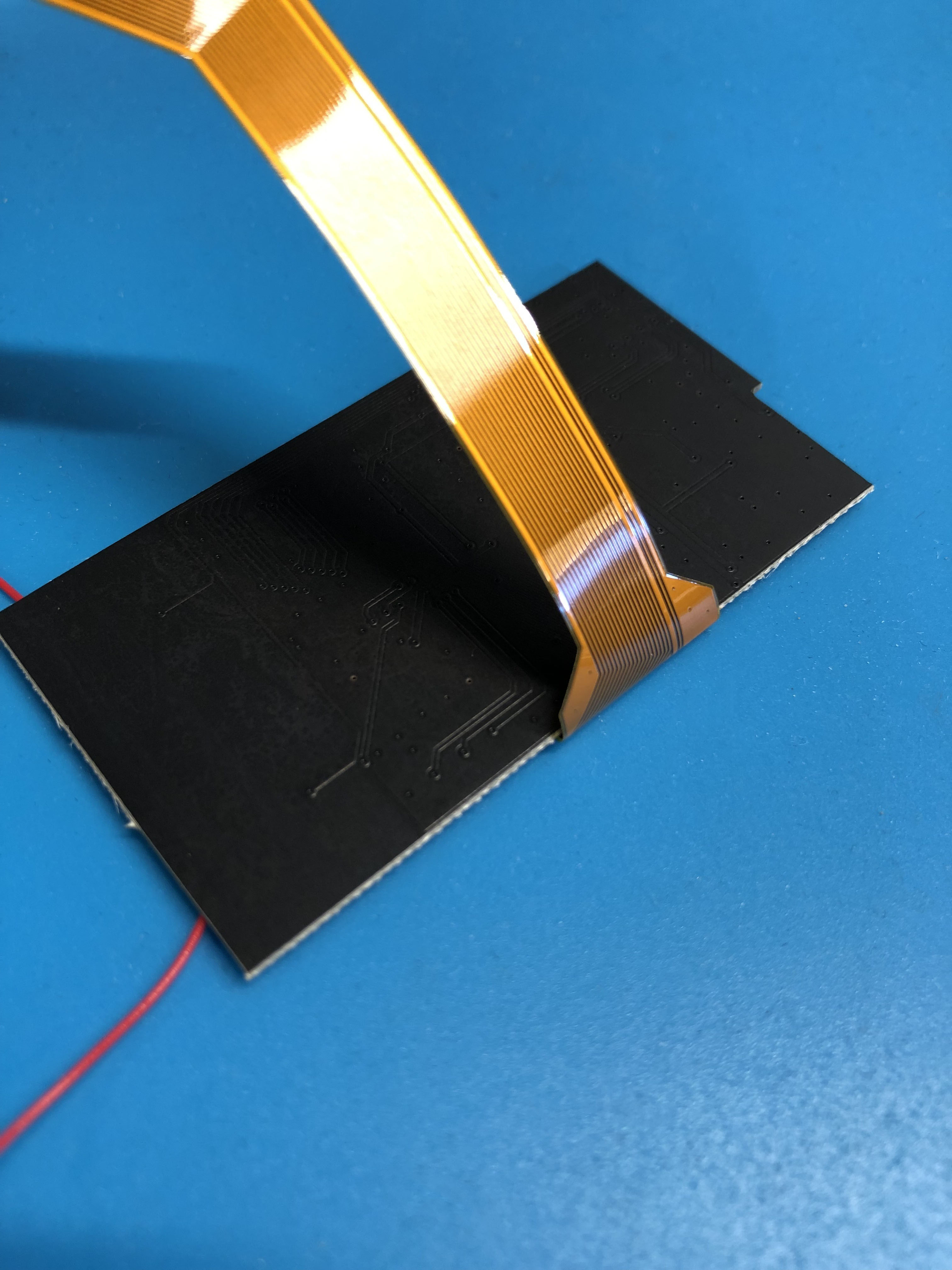
Fold the IPS ribbon behind the IPS control PCB.

Make sure that your ribbon cable is folded completely flush with the PCB. Not doing so will result in not enough lead when feeding ribbon cable through the shell to the motherboard.


Next, we'll pre-solder the connections for this kit.
If installing the TV-Out kit, Apply solder to the labelled connections on the IPS control PCB:
- AV - Video output
- G - Ground

For all kits, apply solder to these connections for brightness control. On the TV-Out kit, this button is used to enable/disable TV-Out function:
- Q12B on the main board
- Tin the solder connection on the ribbon cable

Finally, for the TV-Out kit:
- Pin 3 of the link cable port
- Ground pin of the link cable port

Lay the IPS panel and IPS control PCB flat on your workspace. Carefully connect the FPC connector. This part snaps in like a small building block. Take extra care to ensure the connector is lined up as this piece is extremely delicate.
Apply the double sided adhesive strip to the rear of the IPS control PCB. Fold the PCB over and line it up against the rear of the IPS display. Ensure that the IPS ribbon cable is tucked behind the control PCB as shown.

Insert the IPS display into the front half of the upper SP shell. Install the insulating film on top of the IPS control PCB.
Peel the adhesive backing off of the copper touch pads and install them on the lip of the LCD as seen below. Try to avoid running the wires across the control PCB to avoid interference/accidental input:

Curl the ribbon cable as shown and thread it through the lower-front shell.

For the TV-Out kit, now is the time to solder the two wires to the points labelled AV and G (ground).
If both cables are the same color, you may use a black marker to indicate which wire is for ground to prevent mixing the two later on. Thread these wires through the same slot as the display ribbon cable.

Re-install the rear cover for the LCD section along with the 5 y0 screws. Also re-install the small hinge cover piece which uses the longer J0 screw Be careful not to pinch the ribbon cable during this step.

Flip over the entire assembly.
Connect the IPS ribbon cable to the main board. Latch both sides of the connector to secure the cable in place.
This next step may be a bit easier if you have another object to prop up the IPS display assembly and front shell. We will need to solder all of the required connections at this point. Carefully solder the wires to the pre-soldered connections we've established earlier in the guide.
- For TV Out kit, AV goes to pin 3 of the link cable port pins
- For TV Out kit, G goes to the ground pin
- For all kits, the connection point on the ribbon cable must be connected to Q12B

Reinstall all buttons, membranes, the speaker mesh, speaker, and power switch. Secure the main board with the 3 gold J0 screws to the lower-front housing.
Install the rear shell and a battery to test all functions.
To enable the TV-Out (TV Out version only), press and hold the brightness button for 5 seconds.
Once you confirm all functions are working as expected, you can fully reassemble your console.
- If you have any questions or concerns, please reach out to [email protected]


