Pro Controller Disassembly
This is our guide for disassembling the Nintendo Switch Pro Controller.
- Plastic spudger tool
- Tweezers

Start by removing the two J0 screws on both handles.
Using a Phillips screwdriver for this step will likely strip the screw. You've been warned!

The handles slip off with a gentle pull.

The removal of the handles will reveal 4 silver J0 screws. Remove these and the rear cover pulls off.


Remove the battery before proceeding.
There are 5 J1 screws holding the rear shell to the controller.
The iFixit Mako driver kit will not be long enough to remove two of the deeper screws. We recommend using a longer screwdriver as provided in kits by ExtremeRate or by using one of the standalone drivers for purchase through iFixit.


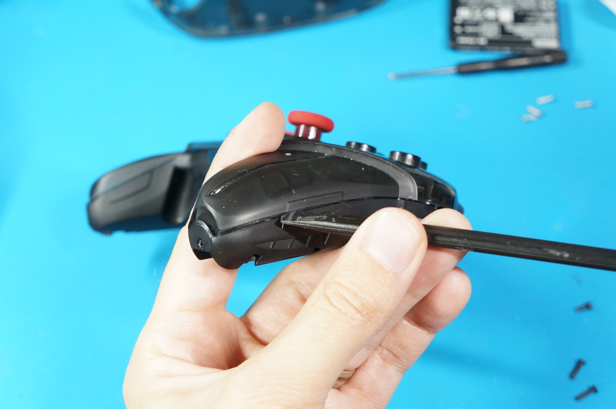
There is some very strong adhesive strips which are used to hold the LRA motors (for HD Rumble) in place. This also has the side effect of holding both halves of the shell together. Using your plastic spudger tool, you can pry the shell halves apart as shown.
Be aware that there is a ribbon cable holding the front half of the controller shell to the rear half. Use caution when removing the rear shell!


Gently unclip the ribbon cable to fully remove the rear shell along with the stick PCB. There is a small black latch that lifts up to allow removal of the cable.

The sticks can be pulled away from the stick boxes using a bit of gentle force.

If you are only looking to replace your buttons. You can skip this entire step and go to the Button PCB Removal.
There are 8 J1 screws to remove here.

The white player LED indicator light pipe can be removed by sliding it up. This will 'unlock' the piece and allow it to be pulled away easily.


Removing the LRA rumble motors is a difficult task. We recommend using the blunt end of a plastic spudger tool to press against the piece from the outside of the rear shell. Quite a bit of force is needed to overcome the strength of the adhesive.

The lower PCB can be lifted up and away from the rear shell. Please note that there is a separate PCB for the battery connection which has one gold J0 screw. Remove this screw and the entire PCB assembly can be removed.

There is a small black bracket which hugs the USB C port area. This houses the sync button as well as the light pipe for the sync indicator LED. Note their locations for future replacement.

Now let's turn our attention to the front controller shell.

There are 4 J1 screws which must be removed.

Unlatch the small FPC ribbon cable for the trigger buttons and remove the cable from its socket. With the connector unlatched, the cable pulls out with ease.

The trigger assembly midframe lifts away from the front shell.

The L and R triggers can be lifted up and unclipped and removed.

The ZL and ZR buttons have a small metal dowel holding them in place. These can be removed using your tweezers. This will release the ZL and ZR buttons and allow them to be removed.

All buttons, membranes, and the button control PCB can be removed!

To reassemble your Pro Controller, simply follow these steps in reverse. Happy modding!
