GBA SP FP Laminated 3" IPS Install Guide
Ribbon cable now includes a touch sensor. Install video will not show this part of the install, please view guide for this information.
This kit includes:
- 1x 3.0 Laminated IPS LCD
- 1x Ribbon Cable
- 2x Foam backing
- 1x Wire for brightness control

First take off the plastic that is protecting the screen.

Next we will place the black foam piece on the bottom of the screen.

Now place the screen into the shell.

Up next is inserting the ribbon cable into the control PCB.

Remove the adhessive from the touch sensor and fold it over onto the screen.

We will then fold the ribbon cable and place the larger foam piece in the back half of the shell in preparation to close the shell.

Now place the back half of the shell onto the front half, with the foam in place.

Now insert your five screws in to hold your shell together.

If you are choosing to install this into an OEM/aftermarket original style shell (with side rail) then you will need to trim the line of plastic highlighted in red. We recommend flush cutters for this process.

Now we will slide the ribbon cable through the shell of the bottom half of the console.

Up next is putting in the hinges of the console, they simply slide in.

The hinge cover comes next, along with the screw that holds it in place.

Following that is our buttons and their membranes, as well as the light pipe and the speaker.

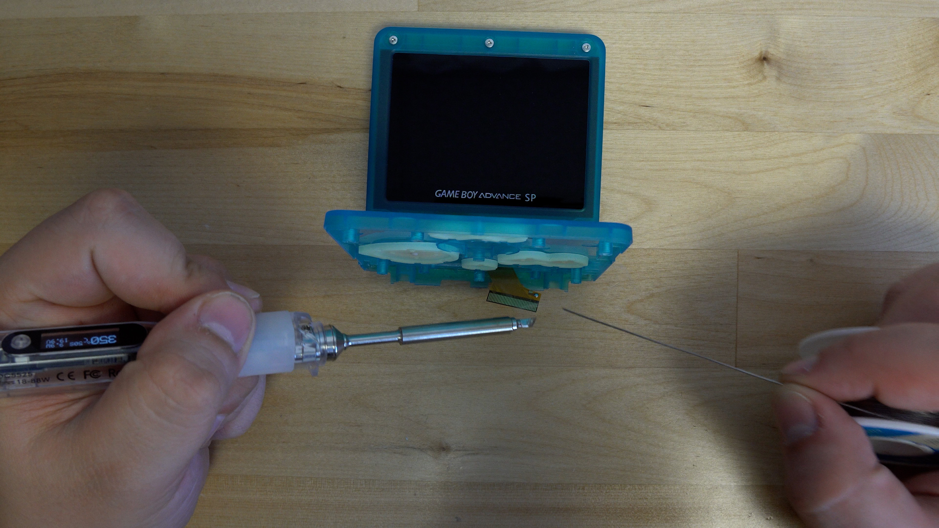
We will then tin the pad on the ribbon cable before soldering the wire into place.

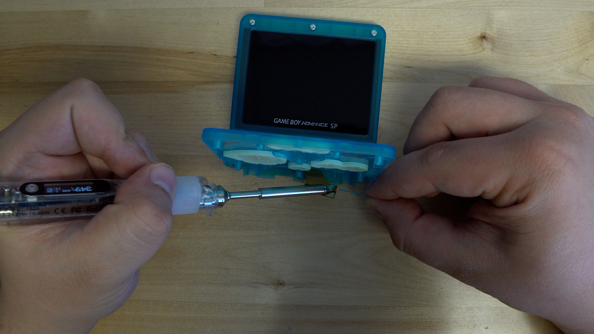
The wire then gets soldered into place.

Now we will insert the ribbon cable into the console to help hold it in place, we will then solder the wire to the brightness button.

Q12B is where you will solder the wire if you do not have a retroglow installed on your console.

If you have a RetroGlow installed on your console then you will need to solder to the BRGHT point.

From here you can put your console back together as normal, and test out your new IPS screen!
To use the brightness button for OSD menu:
- Long hold (3 to 5 seconds) the brightness button to open the OSD
- Press the button once to change the currently highlighted option
- Long hold the brightness button again to switch highlighted options
- To close the OSD simply don't press the brightness button for 5 seconds
To use the touch sensor for OSD menu and brightness:
- Short press (one to two seconds) adjusts brightness levels without entering OSD menu. Long press (3 to 5 seconds) will open OSD menu.
- Long press again to change menu selection.
- Tap/short press to adjust selection in menu.
- To close the OSD simply don't press/tap the sensor for 5 seconds.

