website logo
โŒ˜K
Hand Held Legend Wiki
Modding Tips
Sensitive Touch Sensors
Removing Adhered Screens
Restore Your Original Gameboy Bumper Buttons To Factory
IPS Comparison Info
Headphones Working But Speaker Is Not
Power Switch Cleaning Guide
IPS LCD Dry Test
GBA SP | IPS LCD Dry Test
Soldering Iron Guide
HHL Products
ProGCC V3
GC Pocket Adapter
Open Controller DevKit
Retro-C Cable Information
RetroGlow
ProGCC V2 and V1
Torx Screw Kits
Console Guides
Game Gear
Electrolytic Re-Cap Guide
Nintendo Switch
GameCube
Game Boy (DMG)
Game Boy Pocket
Game Boy Color
Game Boy Advance (AGB)
Game Boy Advance SP
Nintendo DS
Mod Install Guides
Nintendo Switch
Game Gear
GameCube
Game Boy (DMG)
Game Boy Pocket/Light
Game Boy Color
Game Boy Advance (AGB)
Game Boy Advance SP
Atari Lynx
WonderSwan
Product Usage Guides
EZ Flash Upgrade Guide
Writing A Rom To A Flash Cart
๐Ÿงƒ CleanJuice Modules
Game Boy Color
Troubleshooting
๐Ÿ”‰Audio
IPS Troubleshooting Guide
โšกEZ-Flash Omega Troubleshoot
๐Ÿ”‹ Power Switch Is Too Small
Developer Center
OpenJoyPad HID USB Specification
USB Product IDs Used
Nintendo Switch
Affiliate Guidelines
Docs powered by
Archbee
HHL Products
GC Pocket Adapter

Build Guide - GC Pocket Adapter

10min

Assembling the GC Pocket Adapter is super easy! Our kit includes all the parts you'll need to get started!

Video Guide

๏ปฟ

Parts

The kit includes:

  • 1x Shell
  • 2x Buttons
  • 1x Light Pipe
  • 3x Springs (1 extra spring)
  • 3x Steel Balls (1 extra ball)
  • 1x PCB
  • 5x Torx T6 Screws (1 extra screw)

Assembly

Document image
๏ปฟ

Buttons & Light Pipe

The first step towards assembling your Pocket Adapter is to drop the buttons and light pipe into the top half of the shell as shown.

Document image
๏ปฟ

Spring & Ball Setup

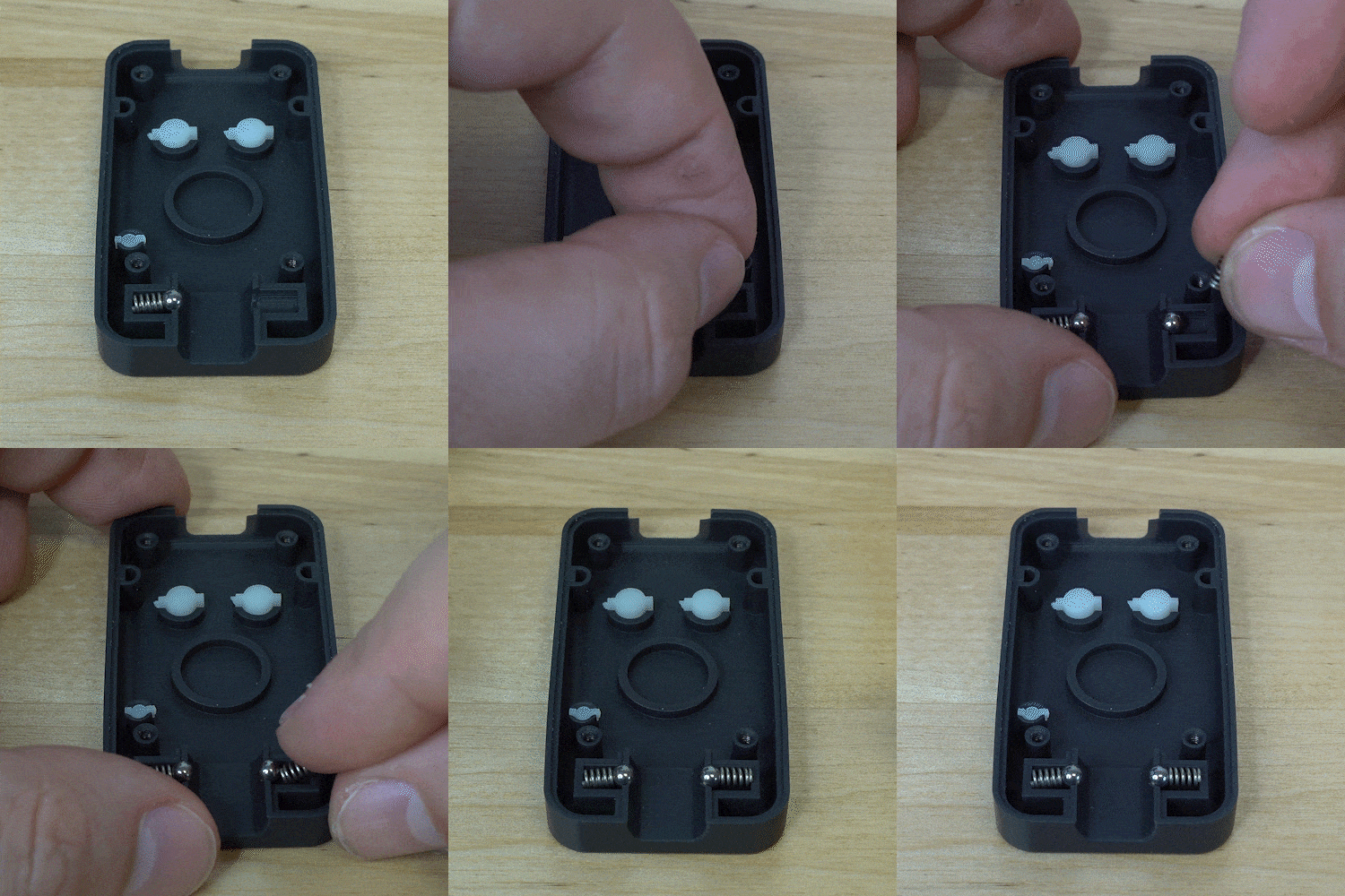
Next we are going to insert the springs and balls that will retain the GameCube controller. The easiest way to do this is to insert the spring first like the one on the left, and then insert the ball like the one on the right. We are then going to insert the last ball and take out PCB and insert it with the buttons facing down.
Document image
๏ปฟ
Document image
๏ปฟ

Now for the final step, put the bottom cover onto the PCB and screw down the four screws that will hold the whole device together using a T6 screwdriver.

Document image
๏ปฟ

Be sure not to over tighten the screws otherwise the buttons will be pressed down on their own from the force of the screws. We recommend tightening the screws just until the PCB is held in place and does not move freely in the shell.

Document image
๏ปฟ

You now have a built Pocket Adapter!

Document image
๏ปฟ

Firmware Flashing

Next up is flashing the firmware to your adapter if it hasn't already had it flashed! Follow our Firmware Update Guide for instructions on what to do next!

Updated 26 Apr 2023
Did this page help you?
PREVIOUS
GC Pocket Adapter
NEXT
Firmware Update Guide - GC Pocket Adapter
Docs powered by
Archbee
TABLE OF CONTENTS
Video Guide
Parts
Assembly
Buttons & Light Pipe
Spring & Ball Setup
Firmware Flashing
Docs powered by
Archbee