website logo
โŒ˜K
Hand Held Legend Wiki
Modding Tips
Sensitive Touch Sensors
Removing Adhered Screens
Restore Your Original Gameboy Bumper Buttons To Factory
IPS Comparison Info
Headphones Working But Speaker Is Not
Power Switch Cleaning Guide
IPS LCD Dry Test
GBA SP | IPS LCD Dry Test
Soldering Iron Guide
HHL Products
ProGCC V3
GC Pocket Adapter
Open Controller DevKit
Retro-C Cable Information
RetroGlow
ProGCC V2 and V1
Torx Screw Kits
Console Guides
Game Gear
Electrolytic Re-Cap Guide
Nintendo Switch
GameCube
Game Boy (DMG)
Game Boy Pocket
Game Boy Color
Game Boy Advance (AGB)
Game Boy Advance SP
Nintendo DS
Mod Install Guides
Nintendo Switch
Game Gear
GameCube
Game Boy (DMG)
Game Boy Pocket/Light
Game Boy Color
Game Boy Advance (AGB)
Game Boy Advance SP
Atari Lynx
WonderSwan
Product Usage Guides
EZ Flash Upgrade Guide
Writing A Rom To A Flash Cart
๐Ÿงƒ CleanJuice Modules
Game Boy Color
Troubleshooting
๐Ÿ”‰Audio
IPS Troubleshooting Guide
โšกEZ-Flash Omega Troubleshoot
๐Ÿ”‹ Power Switch Is Too Small
Developer Center
OpenJoyPad HID USB Specification
USB Product IDs Used
Nintendo Switch
Affiliate Guidelines
Docs powered by
Archbee
Console Guides
Game Boy Advance (AGB)

AGB Capacitor Diagnostic

9min

If you're unsure about whether your GBA console needs a recap, you can test the voltage at these points associated with each electrolytic capacitor.

Unless you have a power supply, measuring the capacitors can be a difficult task unless you know exactly where to probe. We've laid out these locations below so you can test the voltages with AA batteries in the GBA housing (Which blocks the rear side of the PCB).

Measurements are performed with a multimeter in DC voltage mode. Read your multimeter's manual for full details on setup for your device.

Your black probe can be placed on the negative battery terminal labelled BT- on the PCB. Your red probe would go to the point for which you are measuring voltage.

If your readout is significantly less than the voltages listed, the respective capacitor likely needs replacing.

Located near SELECT/START
๏ปฟ

Measurement Locations

CP1

Located near SELECT/START
๏ปฟ

CP2

Located below D-Pad RIGHT
๏ปฟ

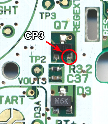
CP3

Located just above START
๏ปฟ

CP4

Located near headphone jack
๏ปฟ

Capacitor Measurements

The following measurements were performed on a known working board that has been recapped.

Note for CP1 - the measurement should directly correlate with the voltage of your batteries combined. If you have two AA batteries that measure 1.5v, the CP1 measurement would be closer to 3v. Similarly, if one battery measures 1.2v, and the other measures 1.5v, the total measurement would be expected to be around 2.7v.

Cap Name

Voltage

CP1

2v to 3v

CP2

5v

CP3

3.33v

CP4

1v

Citations

Board scans - https://circuit-board.de/forum/index.php/Thread/13913-STRIP-CLUB-PCB-Scans/?pageNo=1๏ปฟ

Updated 03 Mar 2023
Did this page help you?
PREVIOUS
Game Boy Advance (AGB)
NEXT
AGB Disassembly Guide
Docs powered by
Archbee
TABLE OF CONTENTS
Measurement Locations
CP1
CP2
CP3
CP4
Capacitor Measurements
Citations
Docs powered by
Archbee